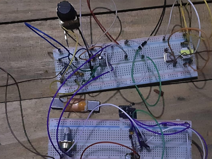
This project involved constructing an AM radio with amplifier and speaker, utilizing components such as a 1MHz Temperature Compensated Crystal Oscillator, LM386 IC, Potentiometer, and other necessary parts.
This project provided me with the opportunity to gain an in-depth understanding of the fundamentals of radio engineering. Constructing an AM radio with amplifier and speaker allowed me to gain hands-on experience with various electronic components and develop a greater appreciation for the complexities of radio engineering.

Introduction
As I learned, alternating currents with frequencies from 20 Hz to 20 kHz are known as audio frequency currents because they can produce a note that is audible when fed into a loudspeaker. Meanwhile, currents with frequencies above 20 kHz are referred to as radio frequency (rf) currents.
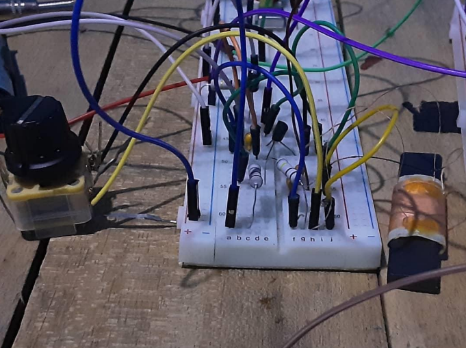
Transmitter
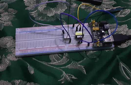
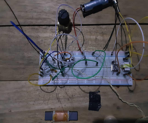
Since the audio cannot propagate on its own, it requires a carrier and that would be provided by the 1 MHz Temperature Compensated Crystal Oscillator. The audio goes from the audio jack into the audio transmitter which transmits the signal to the oscillator. The antenna then propagates the signal. The audio jack of the transmitter when connected to the sound source converts the sound into an audio signal. The audio signal mixes with a carrier frequency (Amplitude modulation). The resulting frequency is sent out by the antenna of the transmitter.
Receiver
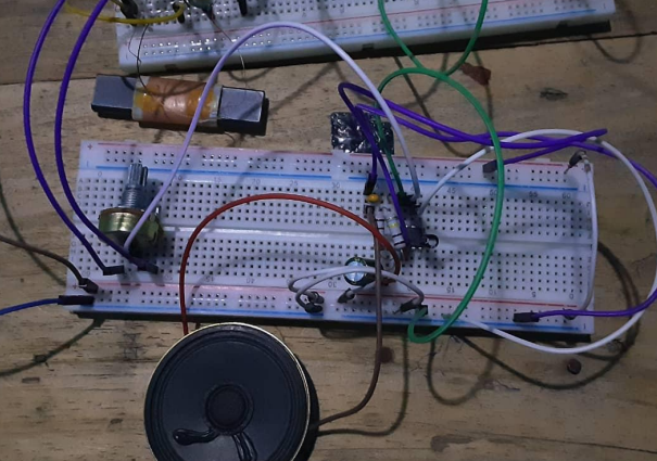
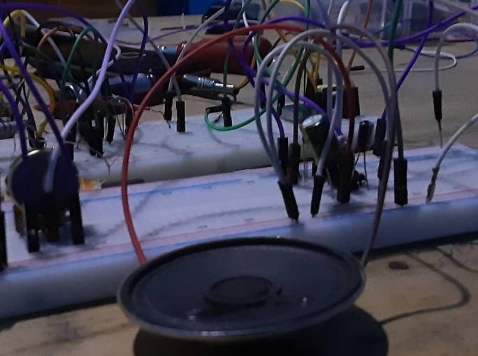
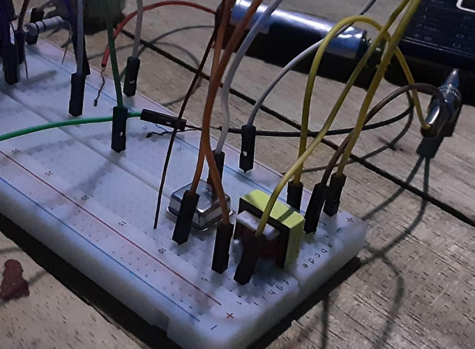
The Antenna connected to the middle of the ferrite loop stick. The MK484 radio integrated circuit would amplify the radio station's frequency, obtained from the tuning of the variable capacitor, then convert to audio (rectifies) and power the earphone. The 1.5 V battery would power this circuit. Anything higher than 1.8V could destroy this chip. I used a ceramic earphone to output the audio at first, later I used a speaker so that the output would be clear enough